Design and construction of soaking furnaces
Overview:
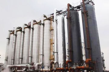
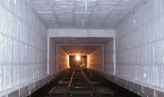
The soaking furnace is a metallurgical industrial furnace for heating steel ingots in the blooming mill. It is an intermittent varied-temperature furnace. The process is that hot steel ingots are demolded from the steelmaking plant, sent to the blooming mill for billeting, and heated in the soaking furnace before rolling and soaking. The furnace temperature can reach as high as 1350~1400℃. The soaking furnaces are all pit-shaped, sized 7900×4000×5000mm, 5500×2320×4100mm, and generally 2 to 4 furnace pits are connected in a group.
Determining lining materials
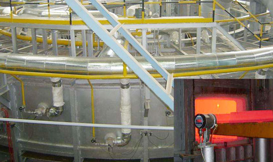
Due to the operating temperatures and working characteristics of the soaking furnace, the inner lining of the soaking furnace often suffers from slag erosion, steel ingot impact and rapid temperature changes during the working process, especially on the furnace walls and the bottom of the furnace. Therefore, the soaking furnace’s walls and bottom linings usually adopt refractory materials with high refractoriness, high mechanical strength, slag resistance, and thermal stability. CCEWOOL ceramic fiber lining is only used for the insulation layer of the heat exchange chamber and the permanent insulation layer on the cold surface of furnace pits. Since the heat exchange chamber is to recover waste heat and the highest temperature in the heat exchange chamber is about 950-1100°C, the materials of CCEWOOL ceramic fiber are generally determined to be high-aluminum or zirconium-aluminum. When using a stacking structure of tiled-laying fiber components, the tile layer is mostly made of CCEWOOL high-purity or standard-material ceramic fiber.
Lining structure:

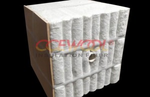
The shape of the heat exchange chamber is mostly square. When lining the side walls and end walls with ceramic fiber, the composite structure of tiled-laying and fiber prefabricated components is often adopted, in which the stacking layer of fiber components can be fixed with angle iron anchors.
Installation arrangement
Considering the structure and characteristics of the angle iron fiber component anchors, in installation, the fiber components need to be arranged in the same direction along the folding direction in sequence, and the ceramic fiber blankets of the same material should be folded into a "U" shape between different rows to compensate for shrinkage.
Post time: Apr-30-2021